📢 $9.99 flat rate shipping in EMEA countries! Ends April 30th - Don't Miss Out!. 🛒 Shop now
Active
ST25TB04K-AC6G6
13.56 MHz short-range contactless memory chip with 4096-bit EEPROM and anticollision functions
| Operating Temp Min Celsius | -40.0 |
| Operating Temp Max Celsius | 85.0 |
| ECCN US | EAR99 |
| ECCN EU | NEC |
| Packing Type | Not Applicable |
| RoHs compliant | N/A |
| Grade | Industrial |
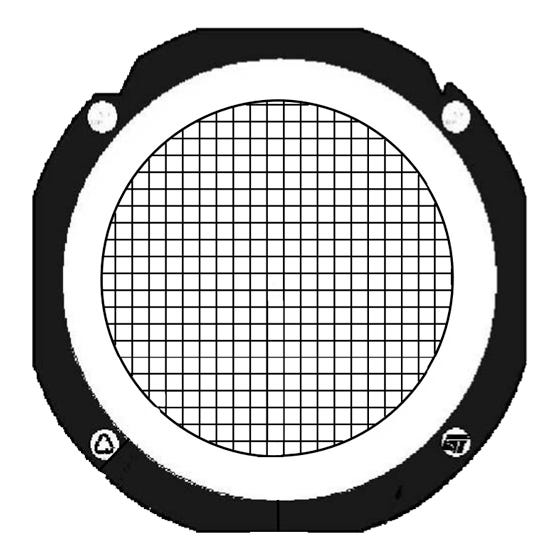
| Package Name | GOLD BUMPED DICE |
The ST25TB04K is a contactless memory, powered by an externally transmitted radio wave. It contains a 4096-bit user EEPROM. The memory is organized as 16 blocks of 32 bits. The ST25TB04K is accessed via the 13.56 MHz carrier. Incoming data are demodulated and decoded from the received...
Read More
|
| Quantity | $ per unit | Savings |
|---|---|---|
| 1-9 | $0.55 | 0% |
| 10-99 | $0.44 | 0% |
| 100-499 | $0.33 | 0% |
| 500 | $0.28 | 0% |
| 500 + |
Contact sales |
|
| Operating Temp Min Celsius | -40.0 |
| Operating Temp Max Celsius | 85.0 |
| ECCN US | EAR99 |
| ECCN EU | NEC |
| Packing Type | Not Applicable |
| RoHs compliant | N/A |
| Grade | Industrial |
| Package Name | GOLD BUMPED DICE |
The ST25TB04K is a contactless memory, powered by an externally transmitted radio wave. It contains a 4096-bit user EEPROM. The memory is organized as 16 blocks of 32 bits. The ST25TB04K is accessed via the 13.56 MHz carrier. Incoming data are demodulated and decoded from the received...
Read More
|

